Search the database of auto parts codes


    previous

    Page 54 - Catalog spare parts BPW LUFT
    P. 54
    Catalogs auto parts for car and truck

    AUTO PARTS

    Page 54 - Catalog spare parts BPW LUFT

    Auto Parts / BPW-EL-Luft 31051601e                                                                              Page 53
    
                                                                                   Axle clamping                     2
    
    
                         Assembly instructions for clamped axle spring seat assemblies                             2.6


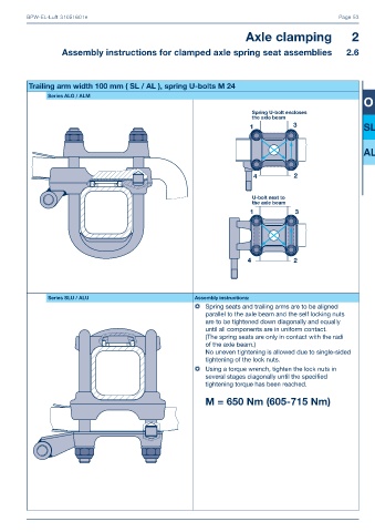
              Trailing arm width 100 mm ( SL / AL ), spring U-bolts M 24
    
                    Series ALO / ALM
                                                                                                                        O
    
    
                                                                                                                        SL
    
    
                                                                                                                        AL


                    Series SLU / ALU                               Assembly instructions:
                                                                       Spring seats and trailing arms are to be aligned
                                                                      parallel to the axle beam and the self locking nuts
                                                                      are to be tightened down diagonally and equally
                                                                      until all components are in uniform contact.
                                                                      (The spring seats are only in contact with the radi
                                                                      of the axle beam.)
                                                                      No uneven tightening is allowed due to single-sided
                                                                      tightening of the lock nuts.
                                                                       Using a torque wrench, tighten the lock nuts in
                                                                      several stages diagonally until the specifi ed
                                                                      tightening torque has been reached.
    
                                                                     M = 650 Nm (605-715 Nm)


    previous
       49   50   51   52   53   54   55   56   57   58   59
    Current Page
    next


    next